
Choosing Cemented Carbide Inserts is a practical decision about workpiece material, cutting conditions, and machine capability. A grade that performs well in cast iron may wear quickly on stainless steel. Insert shape, coating, edge preparation, and chipbreaker geometry also affect tool life and surface finish. Small details matter: a sharp edge can reduce cutting forces, while a tougher grade may better tolerate interrupted cuts.
The raw-material supply chain deserves attention, too. The U.S. Geological Survey’s Mineral Commodity Summaries 2025 estimates global tungsten mine production at 81,000 metric tons in 2024, with China accounting for 67,000 metric tons. Tungsten is a key input for many carbide tools, but these figures describe mined material—not insert availability or price. That distinction is easy to overlook. For a sound choice, compare manufacturer grade recommendations with the actual operation, then check speed, feed, depth of cut, coolant use, and setup rigidity. ISO 513’s material-group framework can help organize workpiece categories, though it cannot select a grade by itself. No chart replaces a controlled test cut. Real shops vary. Start with a stable baseline, record wear and finish, and change one variable at a time. There is rarely one perfect insert; sometimes the first choice is simply a useful trial.
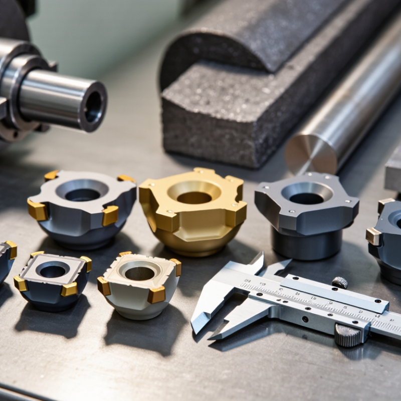
Before comparing insert grades, define the cut precisely. Is it turning, milling, or drilling? Record the workpiece material and hardness, stock allowance, cut length, and whether the edge meets a continuous surface or interrupted features. A roughing pass across a scaled steel bar needs impact resistance; a finishing pass on a thin wall may need a sharp edge and controlled cutting forces. Also note machine rigidity, coolant delivery, and the actual goal: longer tool life, faster cycle time, or a specified surface finish. These goals can conflict. Start with the cut.
Use measurable limits. ISO 3685:1993 uses 0.3 mm average flank wear as a common tool-life test criterion for turning tools; it is a comparison point, not an automatic production target. The U.S. Geological Survey estimated 2023 world tungsten mine production at 78,000 metric tons in its 2024 Mineral Commodity Summaries. That supply figure is useful context, but it cannot tell you which insert suits your operation. Trial a small set under recorded conditions, then compare edge wear, chips, finish, and parts per edge. I would not trust one clean test alone. A setup that behaves well on a rigid bar can fail on a slender component, and shops sometimes overlook that difference. Keep the first trial modest, and change one cutting variable at a time.
Match the insert grade to the workpiece before comparing price or coating. ISO 513:2012 divides machining materials into six groups: steel, stainless steel, cast iron, non-ferrous metals, heat-resistant alloys and hardened materials. Steel often produces long, continuous chips, so a wear-resistant grade can help during steady cuts. Stainless steel work-hardens; a sharp edge and positive geometry can reduce rubbing. Cast iron creates abrasive dust, making edge strength and wear resistance important. Aluminum usually benefits from a sharp, polished cutting edge that helps limit built-up material.
Conditions matter, too. A nickel alloy may need a tougher carbide substrate because heat concentrates near the cutting edge. For interrupted cuts, consider extra toughness; for long, stable cuts, prioritize wear resistance. Not sure? Test one grade on a short run, then inspect the edge and chips. The result may surprise you. The USGS 2024 Mineral Commodity Summaries estimates global tungsten mine production at 78,000 metric tons in 2023. That figure describes raw-material supply, not insert performance—a distinction worth keeping clear. Record workpiece alloy, hardness, coolant use and failure mode; grade charts alone can miss these shop-floor details.
Typical starting cutting-speed ranges for coated-carbide turning, grouped by workpiece material (m/min).
Use the ISO material group as a first guide: P for steel, M for stainless steel, K for cast iron, S for heat-resistant alloys, and H for hardened steel. The ranges are general starting points, not guaranteed recommendations; the appropriate insert grade and speed depend on the specific alloy, hardness, operation, insert geometry, coating, and machine setup. Check the insert supplier’s data before machining.
Choosing a cemented carbide insert starts with the cut, not the catalog. Round inserts spread cutting forces across a strong edge, making them useful for profiling and heavier cuts. Square shapes offer sturdy corners and suit many general turning tasks. Diamond-shaped inserts can reach shoulders and narrow features, but sharper included angles leave less material behind the cutting edge. Check that the chosen shape clears the workpiece and matches the holder’s approach angle. It is easy to overlook clearance. Insert size also matters: match it to the holder, available space, and required cutting depth. An oversized insert may collide with a feature; a very small one can feel less stable.
Cutting geometry should reflect the material and operation. A positive rake and sharp edge can reduce cutting forces in softer materials, while a stronger edge preparation may tolerate interrupted cuts better. Chipbreakers need to suit the feed and depth of cut; chips that stay long or pack around the tool signal a mismatch. Start with the cutting data recommended for the material, then adjust cautiously while checking chip shape, sound, and edge wear. I still find that a geometry that works well in a steady cut may disappoint on a flexible setup. That is not always obvious from a chart. A short trial on the actual machine can reveal the difference.
Choose a coating by matching the dominant failure: flank wear, edge chipping, or heat damage. ISO 513:2012 divides hard-cutting applications into six groups: P, M, K, N, S, and H. Use that classification to identify the workpiece family, then refine the choice using cutting speed, feed, and coolant conditions. For abrasive steel, a TiCN-rich layer can help resist wear. For hotter continuous cuts, Al₂O₃ or AlTiN-based coatings can provide thermal protection. Heat matters.
Coating names alone do not predict insert life. A thick, hard layer may resist abrasion but can make a sharp edge more vulnerable to chipping in interrupted cuts. In practical trials, inspect the worn edge after a short, repeatable run: a polished flank suggests abrasion, while a crater near the cutting edge points to heat and chip contact. Compare inserts at the same speed, feed, depth, and coolant setting; otherwise, the result is hard to trust. ISO 513 is a classification standard, not a performance guarantee, so treat its six groups as a starting point. I would not claim one coating fixes every failure. Edge preparation and machine rigidity can overturn the choice. A modest trial can reveal more than a catalog table.
Before choosing cemented carbide inserts, record the real cutting conditions: workpiece material, hardness, operation, and cut depth. Note whether the job involves continuous turning or interrupted cuts, such as a surface with keyways. These details affect edge strength and heat resistance. Small details matter.
Verify the machine can hold the selected insert securely and run at the required speed and feed. Check the toolholder pocket, insert shape, clamping screw, and available clearance. A mismatched seat can cause vibration or uneven wear, even when the insert grade seems suitable. Also confirm spindle power and rigidity, especially on older or lightly built machines. Check coolant delivery, too. A stream that misses the cutting zone may offer little benefit.
Compare the machine’s actual operating range with the insert supplier’s recommended cutting data, then make a controlled test cut. Watch for chatter, built-up material on the edge, and changes in chip shape. Reduce the feed or speed if the cut sounds unstable, and inspect the edge after a short run. The first setup may not be perfect; machine condition and workpiece variation can complicate the choice. Record adjustments so the next trial is based on evidence, not guesswork.
Use this guide to compare common insert applications with practical starting conditions and machine checks. Cutting data are indicative ranges; confirm them against the insert supplier’s recommendations and the actual workpiece condition.
| Workpiece and Operation | Typical Insert Considerations | Indicative Starting Conditions | Machine and Setup Compatibility Checks | When to Adjust |
|---|---|---|---|---|
| Low-carbon or alloy steel Continuous turning | ISO P grade; coated carbide is commonly used. Choose a robust edge for interrupted cuts and a sharper edge for light finishing. | Cutting speed: 150–250 m/min Feed: 0.15–0.35 mm/rev Depth of cut: 1–3 mm | Confirm the insert seat and toolholder match the insert shape and size. Check spindle power, workholding rigidity, tool overhang, and coolant delivery. | Reduce speed for hardened material, long overhangs, or unstable setups. Use a tougher edge for scale or interrupted cuts. |
| Austenitic stainless steel Turning | ISO M grade with a sharp, positive cutting edge can help limit work hardening and cutting forces. Select a chipbreaker suited to the feed and depth of cut. | Cutting speed: 100–180 m/min Feed: 0.10–0.25 mm/rev Depth of cut: 0.5–2 mm | Check that the machine can maintain a steady feed without rubbing. Verify tool rigidity and provide consistent coolant where the process calls for it. | Avoid dwelling or very light rubbing cuts. Lower speed if heat, built-up edge, or rapid flank wear appears. |
| Grey cast iron Turning | ISO K grade; a wear-resistant edge is often suitable for stable cuts. Consider a tougher edge if the casting has a hard skin or interruptions. | Cutting speed: 120–220 m/min Feed: 0.15–0.35 mm/rev Depth of cut: 1–3 mm | Assess machine rigidity and chip or dust extraction. Dry cutting is common in many cast-iron operations, but follow the tool and process recommendations. | Use a tougher edge for scale, sand inclusions, or interrupted cuts. Reduce cutting data if vibration or edge chipping occurs. |
| Aluminum alloy Turning | A sharp, polished, often uncoated carbide edge can help reduce built-up material. Use geometry intended for non-ferrous metals. | Cutting speed: 300–800 m/min Feed: 0.10–0.35 mm/rev Depth of cut: 0.5–3 mm | Confirm the spindle’s maximum speed is sufficient and that the workpiece is securely clamped. Check toolholder balance and chip clearance at higher speeds. | Use the lower end for large diameters or limited spindle speed. Adjust coolant or lubrication and chipbreaker choice for chip control. |
| Steel Face milling | Use a milling insert and cutter body designed for the required operation. A tougher grade and suitable edge preparation may help with interrupted engagement. | Cutting speed: 120–220 m/min Feed per tooth: 0.08–0.20 mm/tooth Axial depth of cut: 0.5–3 mm | Verify cutter diameter, insert pocket compatibility, spindle interface, available power, and feed capability. Keep tool overhang short and ensure secure workholding. | Start conservatively if the cutter has many teeth or the setup is less rigid. Investigate runout, vibration, and uneven insert wear before increasing feed. |
| Hardened steel Finishing turn | Use a carbide grade specifically recommended for the hardness and operation; not all carbide inserts are suitable for hard turning. Keep the edge and setup stable. | Cutting speed: 60–150 m/min Feed: 0.05–0.15 mm/rev Depth of cut: 0.1–0.5 mm | Check actual material hardness, machine rigidity, spindle condition, and toolholder stability. Confirm whether the insert specification covers the workpiece hardness. | Reduce speed or feed if the edge chips or the surface finish deteriorates. For very high hardness or demanding tolerances, compare with other tooling options. |
Important: These ranges are general starting points, not guaranteed limits. Actual results depend on carbide grade, coating, insert geometry, workpiece hardness, coolant strategy, machine condition, and setup rigidity. Confirm units, maximum spindle speed, power, holder fit, and cutting direction before machining; make controlled adjustments while monitoring chip shape, temperature, vibration, and tool wear.