
How to Choose the Best Automotive Motor Tester?
Choosing the right Automotive Motor Tester begins with the faults you need to find. A small repair shop may need reliable checks for starter motors, alternators, and charging circuits. A specialist workshop may also need waveform analysis, load testing, and detailed data capture. The best choice is not always the model with the largest screen. It is the tester that answers your everyday diagnostic questions accurately, safely, and without slowing down the work. A useful principle, paraphrased from automotive technology author and educator James D. Halderman’s diagnostic approach, is: “Measure the system before replacing a part.” That habit matters.
Look closely at voltage range, current capacity, test modes, lead quality, and compatibility with the vehicles you service. A clear display helps when readings must be checked beside a noisy engine bay. Durable leads matter when tools are used daily, not just during demonstrations. Consider whether the tester stores results or connects to workshop software. Check the manual, calibration guidance, warranty, and available support before buying. Small details count.
Still, a tester cannot replace sound judgment. A low reading may come from a weak battery, a poor connection, or a failing motor. The tool shows evidence; the technician must interpret it. This guide will compare essential features, explain common trade-offs, and help match a tester to real workshop needs. Some specifications look impressive on paper. Their value depends on the jobs you actually perform.
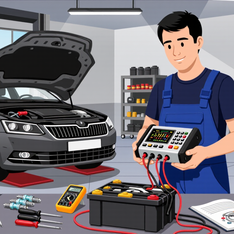
Identify Motor Type and Voltage Class: 12 V, 48 V, 400 V, or 800 V
Choosing a motor tester starts with the motor’s voltage class, not the vehicle’s age or size. A 12 V accessory motor may need basic resistance, continuity, and current checks. A 48 V mild-hybrid system calls for equipment rated for that voltage and its switching behavior. Traction motors in 400 V and 800 V vehicles require testers designed for high-voltage circuits, with suitable measurement limits and isolation. Close enough is not good enough.
Motor type matters too. Brushed DC motors, induction motors, and permanent-magnet motors produce different readings and need different test functions. Check the tester’s specifications for supported motor types, voltage range, and measurement method. For example, a resistance check on a disconnected 12 V blower motor is not the same task as assessing an EV traction motor’s phase windings. That distinction is easy to miss.
Before testing, confirm the circuit voltage from service information and inspect the tester leads for damage. Use equipment rated for the system, and follow the vehicle’s shutdown and isolation procedure for high-voltage work. Never assume a tester is suitable just because its display shows a large number. A clear display helps, but it does not prove safe isolation. I have seen voltage labels create false confidence; checking the actual measurement category and limits takes an extra minute.
How to Choose the Best Automotive Motor Tester? — Identify Motor Type and Voltage Class: 12 V, 48 V, 400 V, or 800 V
| Voltage class | Common automotive applications | Typical motor types | Tester capabilities to look for | Checks and selection considerations | Safety considerations |
|---|---|---|---|---|---|
| 12 V | Starter motors, cooling fans, fuel pumps, window lifts, seat adjusters, and other auxiliary loads. | Brushed DC motors are common; some auxiliary systems use electronically commutated motors. | Low-voltage power and load testing; current measurement; voltage-drop testing; continuity and resistance checks; support for the relevant motor-control electronics where applicable. | Check operating current, starting current, supply polarity, connector pinout, and whether the motor is tested directly or through its controller. A basic multimeter alone may not reveal performance under load. | Use appropriate fused leads and avoid shorting the battery supply. Follow vehicle procedures when working near high-current starter circuits. |
| 48 V | Mild-hybrid systems, belt starter-generators, integrated starter-generators, and higher-power auxiliary systems. | Commonly three-phase permanent-magnet synchronous motors or other inverter-driven motor designs; exact configuration varies by vehicle. | Testing compatible with the system’s maximum voltage; three-phase winding measurements; current and waveform analysis; communication or inverter diagnostics when supported. | Confirm whether the system is a 48 V architecture and identify the motor and inverter separately. Select equipment for the actual maximum operating voltage, not only the nominal class. | Although below typical high-voltage traction levels, 48 V systems can deliver hazardous current. Isolate and verify the circuit according to the vehicle service procedure. |
| 400 V class | High-voltage traction drive systems in battery-electric and plug-in hybrid vehicles. | Usually inverter-driven three-phase permanent-magnet synchronous or induction motors. | High-voltage-rated measurement inputs; phase-to-phase and winding-balance checks; suitable insulation-resistance testing for an isolated motor; inverter and position-sensor diagnostics where supported. | Verify the tester’s maximum voltage rating, measurement category, leads, and accessories. Determine whether the required test is for the motor, inverter, or complete drive unit; these require different procedures. | High-voltage work requires trained personnel, vehicle-specific isolation procedures, and verification of absence of voltage. Disconnect the motor from the inverter before insulation testing unless the manufacturer explicitly permits otherwise. |
| 800 V class | Higher-voltage battery-electric traction systems and associated drive units. | Typically inverter-driven three-phase permanent-magnet synchronous or induction motors. | Equipment and accessories rated for the system’s maximum possible voltage; appropriate high-voltage measurement and insulation-test functions; support for the specific motor and inverter diagnostic requirements. | Do not assume an 800 V system operates at exactly 800 V. Check the battery’s voltage range and the manufacturer’s service specifications, then choose a tester with adequate ratings and margin. | Use only equipment approved for the intended high-voltage task. Follow lockout, isolation, discharge, and voltage-verification procedures, and observe specified waiting times. |
Selection note: Voltage class is only a starting point. Confirm the motor technology, inverter arrangement, maximum system voltage, connector and sensor type, and the vehicle manufacturer’s test procedure. Insulation-test voltage and connection methods must follow the relevant service documentation.
BUSINESSES USING CAMASTER