
Top 10 RF Divider Manufacturers for Global Buyers
Choosing an Rf Divider is not just a search for a familiar brand. Global buyers must match frequency range, port count, power handling, impedance, and connector type to the actual system. A divider that looks suitable on a catalog page may still disappoint when insertion loss, amplitude balance, or isolation matters in a working setup. Small details count. A loose connector can complicate testing; a few decibels of unexpected loss can affect the link budget.
David M. Pozar’s Microwave Engineering provides a respected foundation for understanding microwave networks. A buyer-focused paraphrase of its design lessons is: “Choose a divider by how its measured performance fits the system, not by its label alone.” That is a paraphrase, not a direct quotation. This guide compares ten manufacturers through practical questions: Do their published specifications cover the required band? Are test data and product options clear? Can buyers confirm lead times, support, and configuration details? These checks help distinguish a promising datasheet from a dependable sourcing choice. Still, no ranking can replace application-specific testing. That part is easy to forget. The manufacturers below offer a starting point for comparison, not a universal verdict; a careful buyer should verify the exact model against the intended frequency, environment, and installation.
Understanding RF Dividers and Their Role in Signal Distribution
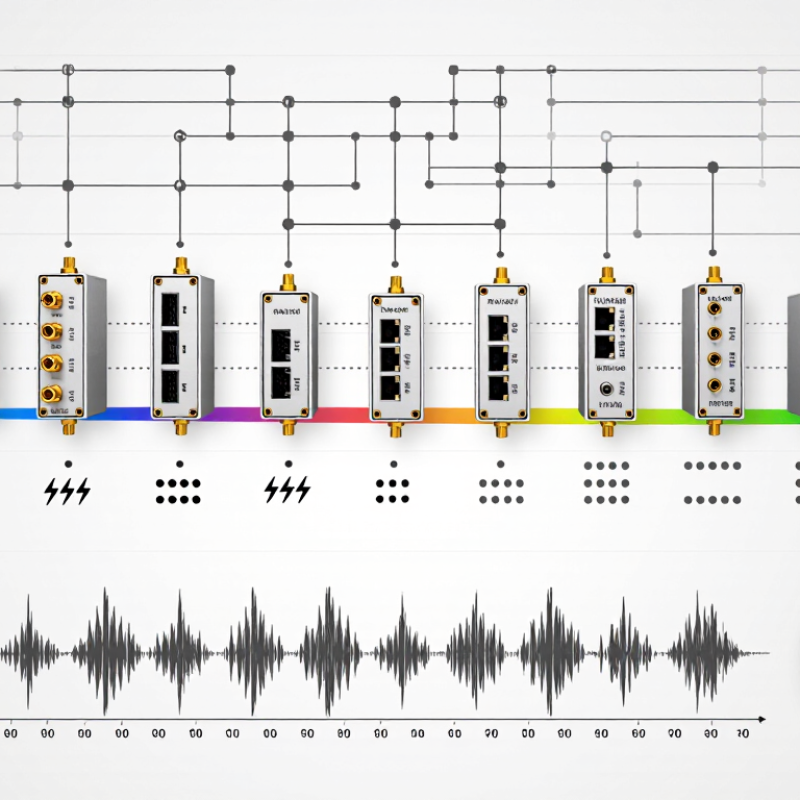
An RF divider distributes one input signal across multiple output paths. In a two-way equal divider, each output receives half the input power, equivalent to about 3 dB less. Real devices add insertion loss, so measured output levels may be lower. That is normal. The divider’s frequency range, impedance, port isolation, and power rating all affect whether it suits a system. A mismatch at one port can also disturb the others, especially in sensitive measurement or communications setups.
Choosing a divider starts with the signal path, not just the port count. Check whether outputs need equal or unequal power, and confirm the operating band covers the full signal range. On a lab bench, short cables and consistent connectors make comparisons more reliable. Terminate unused ports as specified; leaving one open can create reflections. A datasheet cannot predict every installation. Nearby components, cable bends, and mounting details may change performance, so verify the assembled system with suitable test equipment. The first bench result may look fine and still mislead. A second measurement, with the actual cables and loads, is often worth the extra few minutes.
Top 10 RF Divider Manufacturers for Global Buyers - Understanding RF Dividers and Their Role in Signal Distribution
| No. | Evaluation Dimension | Technical Context | What Buyers Should Confirm |
|---|---|---|---|
| 1 | Operating Frequency Range | An RF divider distributes an input signal across multiple output ports within a specified frequency band. Performance is characterized over the stated operating range. | Check that the complete application band is covered and review insertion loss, isolation, and balance specifications across that band—not only at a single test frequency. |
| 2 | Number of Output Ports | Common passive divider configurations include two-, four-, and eight-way designs. More outputs generally require a greater share of the available input power to be distributed. | Select the required number of outputs and confirm whether unused ports need to be terminated to maintain the specified performance. |
| 3 | Ideal Split Loss and Excess Loss | For an equal N-way split, the ideal per-output power division is 10 log10(N) dB: approximately 3.01 dB for two ways, 6.02 dB for four ways, and 9.03 dB for eight ways. Real devices add excess loss. | Distinguish theoretical split loss from the manufacturer’s specified insertion loss, and include the divider’s loss in the link budget. |
| 4 | Amplitude Balance | Amplitude balance describes the difference in output levels between ports under specified test conditions. Lower imbalance can help maintain consistent signal levels across branches. | Compare the maximum amplitude imbalance over the required frequency band and check the test conditions used for the specification. |
| 5 | Phase Balance | Phase balance indicates how closely the output phases match. It can be important in phased-array, beamforming, and other systems that combine or coordinate multiple RF paths. | Confirm phase-balance limits, frequency coverage, and whether the stated value applies to all output-port pairs. |
| 6 | Port Isolation | Isolation describes the attenuation of signal coupling between output ports. Higher isolation can reduce interaction between connected branches. | Review the minimum isolation across the operating band and verify that the specification matches the intended system configuration. |
| 7 | Impedance and VSWR | Many RF systems use a nominal 50-ohm impedance. Voltage standing wave ratio (VSWR) is one measure of impedance matching; lower VSWR generally indicates less reflected power. | Match the divider’s impedance to the system and check input and output VSWR over the full frequency range. |
| 8 | Power Handling | Power ratings depend on the device design and specified operating conditions. In a passive equal split, input power is divided among the outputs, while losses and temperature affect practical limits. | Confirm the maximum input and per-port power ratings, ambient-temperature conditions, and any derating requirements. |
| 9 | Divider Topology | Wilkinson dividers are a common passive topology. In a conventional equal-split design, isolation resistors help provide output-port isolation while the network is matched at its design frequency. | Ask which topology is used and whether its bandwidth, isolation, and power characteristics suit the application. |
| 10 | Mechanical Interface and Environment | Housing, connector type, mounting method, and environmental rating affect installation and reliability. Connector choices must be suitable for the frequency and power requirements. | Verify connector compatibility, package dimensions, mounting details, operating temperature, and any required environmental or compliance documentation. |
BUSINESSES USING CAMASTER